← All skills

Skill

Statistical modeling

Describing measured behavior with a model that predicts it. The Odin's error model: a relocalization offset plus first-order Gauss-Markov noise, checked on held-out data.

2 log entries1 project

Advanced Robotics at UWBest example

An error model for the Odin

Analysis code

Also shows: State estimationExperiment designPython

The question wasn't how accurate the Odin is but whether the sentry could rely on it alone, and one accuracy number can't answer that: the nav stack needs to know how the error behaves, whether it grows, and what happens when something goes wrong. So I designed the October 3 campaign around those questions (figure-8 laps, a long hold, repeated relocalizations and covered-sensor trials, all against mocap) and fit a small model to it: the true pose, plus an offset drawn each time the Odin relocalizes into its map, plus first-order Gauss-Markov noise: correlated over time, but decaying.

poseout(t)=posetrue(t−τd)⊕ε(t),τd≈0
ε(t)=R(ψ)Tbk+η(t)
bk∼N(0, diag(σb2)),per relocalizationk
ηi[n+1]=aiηi[n]+σi1−ai2wi[n]
ai=e−Δt/τc,i,Δt=0.1s

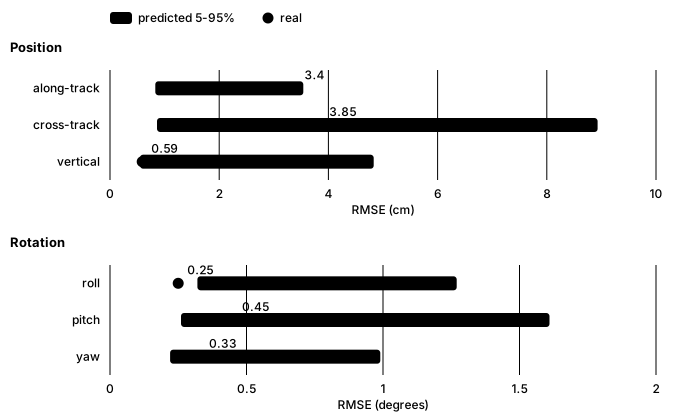
Splitting the error this way was the key decision. The offset from each relocalization turned out to be the largest term, which one overall noise figure would have blurred, and modelling the noise as decaying showed the error stays bounded instead of drifting. To check the model wasn't just describing the data it was fit to, I refit it without one session, simulated it many times along that session's real path (a Monte Carlo check), and asked whether the real error fell where the simulations said it would. It did: its real error there, 5.1 cm horizontal and under half a degree, matched the prediction on all six axes (roll came in just under its predicted range, still within the test). That made the recommendation clear: the Odin can be the sentry's only localization, kept on the turret major, where it swivels independently of the turret and the chassis. We tried it in several mount locations and found the occlusions made little difference. The nav stack only has to handle a rare wrong relocalization, and the output pausing while the sensor is covered.
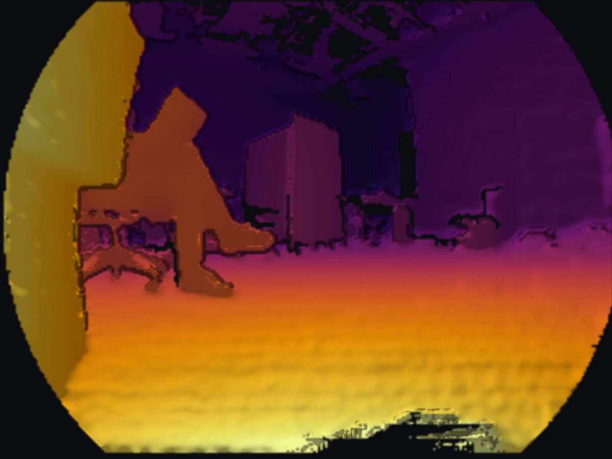
Depth image from the Odin, colored from yellow for near to purple for far, in its round fisheye frame: a wall close by on the left, a person sitting in a chair, and boxes and furniture across the room
What the Odin sees: a depth image from its recordings, near in yellow and far in purple.
Chart: for each axis, the Odin's real error on a held-out session as a dot against the model's predicted range as a bar; along-track, cross-track and vertical position, and roll, pitch and yaw
The hold-out check: the model, refitted without one session, predicts that session's error. Every axis passes; roll comes in just under its predicted range.

Advanced Robotics at UW

The same check for a 2D lidar

Code

Also shows: ROS 2State estimation

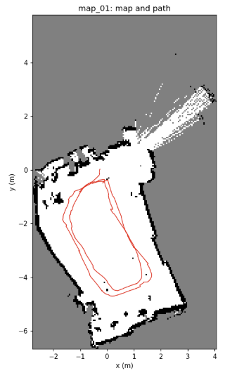
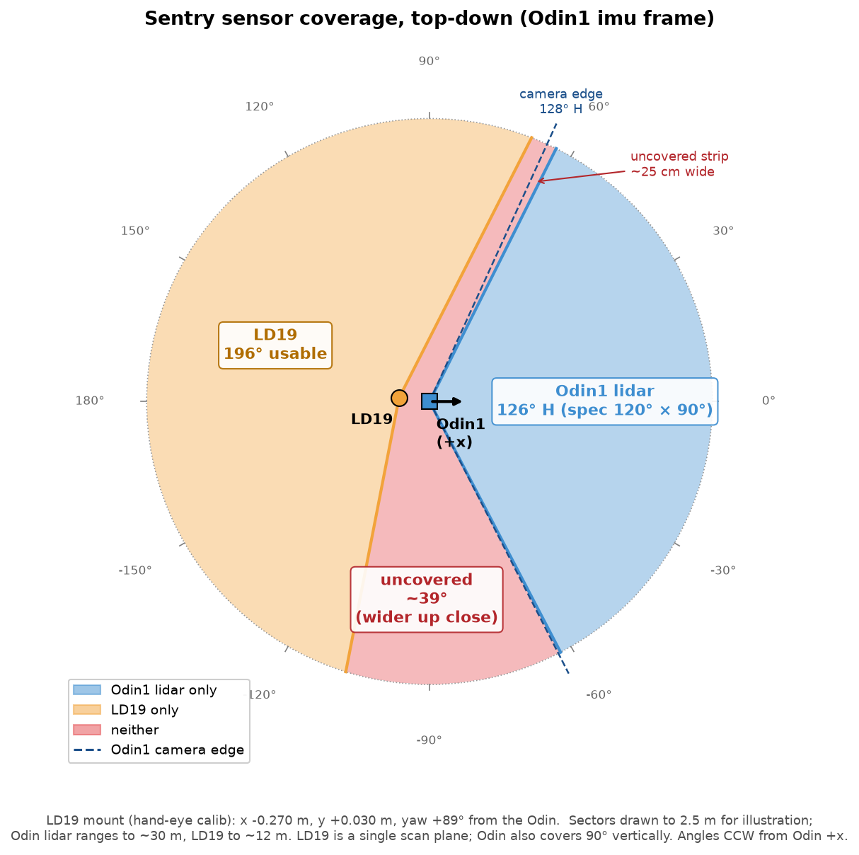
I ran the same characterization on a WayPonDEV LD19 2D lidar, for obstacle mapping, with the Odin providing the pose. It scans at a steady 10 Hz with 8–14 ms of jitter, about 503 points per scan 0.72° apart, and skips 1–2% of scans. Range noise is 3–6 mm at 1–2 m, 6–11 mm at 2–3 m and 7–28 mm at 3–5 m: well under a 5 cm map cell, even at 5 m. At most 0.2% of returns are isolated false points and 1–2.4% are outliers, mostly at object edges where a beam half-hits the edge and half the background, which a filter removes easily. It never dropped off USB in the 40 minutes it ran, and the longest gap between scans was one skipped scan. The LD19 was good enough for our use, but we bought a 3D lidar anyway: the Odin's field of view is small, and a 3D lidar sees much more of the area around the robot.

Occupancy map of a cluttered room, about 7 by 12 meters, with the robot's pushed path drawn in red as two loops
The room mapped with the LD19's scans, placed by the Odin's poses (5 cm cells), with the 24.5 m path the robot was pushed along in red.
Top-down diagram of the sentry's sensor coverage: the Odin's lidar covers a 126 degree wedge to the front, the LD19 a 196 degree arc behind, and a 39 degree wedge between them is covered by neither
What the two sensors see on the sentry, from the measured mounting: a 39° wedge is covered by neither.