← All skills

Skill

Python

My main language for robotics tooling and research code: the VLA evaluation harness, my additions to the lab's arm planner, the Quest teleop, and the analysis behind ARUW's localization study.

9 log entries4 projects

Benchmarking VLAs for ARCHITECTBest example

An evaluation harness for any VLA

Code

Also shows: Robot learning

Every VLA ships its own server, and they don't agree on how to talk: openpi's π0 and π0.5 use WebSockets, GR00T uses ZMQ and MolmoAct2 uses HTTP. I wrote one harness that hides all of that behind a single interface: a new model, task or whole benchmark is a short YAML file, not new code.

On the robot, the harness asks the policy for a chunk of actions, runs eight of them open loop, then asks again, recording the scene and wrist cameras throughout. The operator scores each rollout, everything is saved as it goes so an interrupted run resumes, and one script turns the results into success rates per task and per prompt.

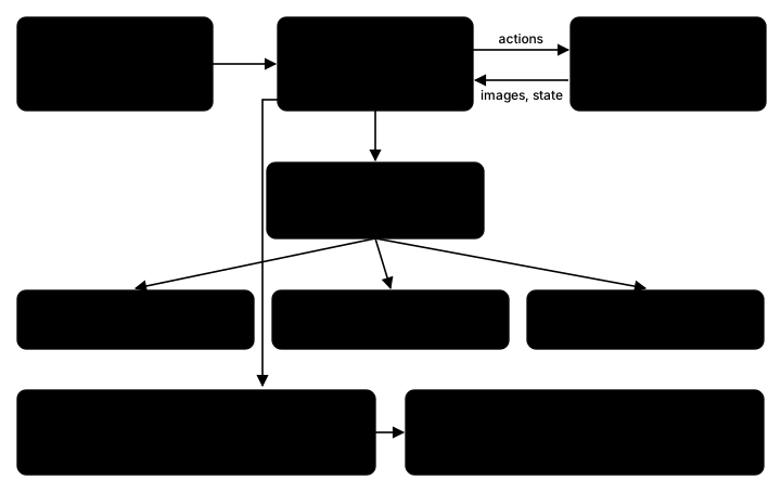
Diagram of the harness: YAML configs feed run_eval.py, which drives the DROID robot and asks one policy client for chunks of actions; the client reaches π0 and π0.5 over WebSocket, GR00T N1.7 over ZMQ and MolmoAct2 over HTTP; every rollout's scores and videos go to a results folder that compute_results.py turns into CSVs
How a run fits together.
π0.5 putting the banana on the plate.

OpenDubs

N arms, one planner: ArmGroup

Pull request

Also shows: Motion planningSimulation (MuJoCo)

The lab plans with its own MuJoCo planning library, mj_manipulator, which planned one arm at a time. With two arms on one torso, two plans that are each safe can still hit each other. I added an ArmGroup to it that plans all arms' joints together, so every step is checked arm against arm. On the clip's goals, the two arms planned separately collide in 58 of 210 frames; ArmGroup's plan bends one gripper about 16 cm around the other and touches in none. The same group plans to joint goals, gripper poses and lockstep Cartesian paths, keeps 5 mm between all geometry, retimes the trajectory at 125 Hz, and re-checks it at every sample. I made single-arm planning a one-arm group, and ArmGroup is what plans both arms on the robot today.

The same goals, each arm planned on its own (left, red while they intersect) and planned together by ArmGroup (right). The lines are the grippers' paths. MuJoCo, real time.
A two-arm handover planned with ArmGroup in MuJoCo (the can is carried kinematically).

Advanced Robotics at UW

An error model for the Odin

Analysis code

Also shows: State estimationExperiment design

The question wasn't how accurate the Odin is but whether the sentry could rely on it alone, and one accuracy number can't answer that: the nav stack needs to know how the error behaves, whether it grows, and what happens when something goes wrong. So I designed the October 3 campaign around those questions (figure-8 laps, a long hold, repeated relocalizations and covered-sensor trials, all against mocap) and fit a small model to it: the true pose, plus an offset drawn each time the Odin relocalizes into its map, plus first-order Gauss-Markov noise: correlated over time, but decaying.

poseout(t)=posetrue(t−τd)⊕ε(t),τd≈0
ε(t)=R(ψ)Tbk+η(t)
bk∼N(0, diag(σb2)),per relocalizationk
ηi[n+1]=aiηi[n]+σi1−ai2wi[n]
ai=e−Δt/τc,i,Δt=0.1s

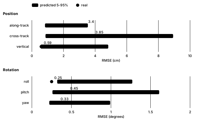
Splitting the error this way was the key decision. The offset from each relocalization turned out to be the largest term, which one overall noise figure would have blurred, and modelling the noise as decaying showed the error stays bounded instead of drifting. To check the model wasn't just describing the data it was fit to, I refit it without one session, simulated it many times along that session's real path (a Monte Carlo check), and asked whether the real error fell where the simulations said it would. It did: its real error there, 5.1 cm horizontal and under half a degree, matched the prediction on all six axes (roll came in just under its predicted range, still within the test). That made the recommendation clear: the Odin can be the sentry's only localization, kept on the turret major, where it swivels independently of the turret and the chassis. We tried it in several mount locations and found the occlusions made little difference. The nav stack only has to handle a rare wrong relocalization, and the output pausing while the sensor is covered.
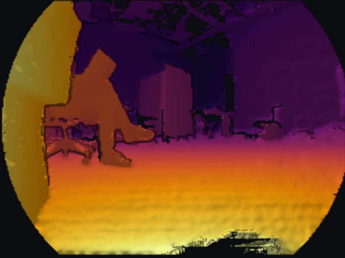
Depth image from the Odin, colored from yellow for near to purple for far, in its round fisheye frame: a wall close by on the left, a person sitting in a chair, and boxes and furniture across the room
What the Odin sees: a depth image from its recordings, near in yellow and far in purple.
Chart: for each axis, the Odin's real error on a held-out session as a dot against the model's predicted range as a bar; along-track, cross-track and vertical position, and roll, pitch and yaw
The hold-out check: the model, refitted without one session, predicts that session's error. Every axis passes; roll comes in just under its predicted range.

OpenDubs

Teleop with a Meta Quest, in the browser

Code

Also shows: Teleoperation

For demonstrations and live driving, I built teleop with a Meta Quest. The apps I tried had no passthrough and left me dizzy, so I wrote my own: instead of an app on the headset, the robot serves a page the Quest's browser opens in AR, so the operator still sees the room, and the page streams both controllers' poses, grip and trigger to the robot over a websocket. Holding a grip engages its arm, and the trigger works the gripper. The headset's page goes dark once it enters AR, so the robot also broadcasts that live telemetry to any other browser pointed at it, and someone at a laptop can watch exactly what the operator is sending. It matches the old SDK's interface, so switching was a one-line change. I built it against the arms in MuJoCo first; at first the loop couldn't keep up, and the bottleneck turned out to be publishing the sim viewer over the network, not the control.

Teleop on the robot after the speed-ups.
My teleop loop in MuJoCo, fed two scripted hands (the spheres): the repo's limits (left) and raised ones like the robot's now (right).

OpenDubs

Running both arms at once

Bimanual refactor

Also shows: ROS 2Motion planning

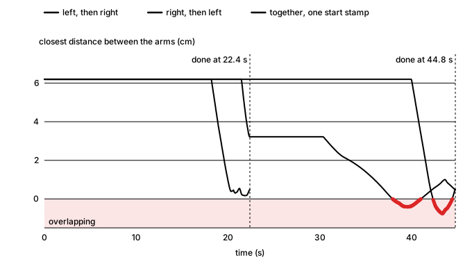
A two-arm plan is only safe if both arms run it together: it was checked with each arm where the other would be at the same instant. On hardware, though, mj_manipulator_ros, the lab's layer that runs those plans on the robot, ran multi-arm plans one arm after the other, which doubled the time and passed through states the planner never checked. Replaying the crossing plan that way in MuJoCo and checking every fourth of its states, the arms intersect in 97 of 1,400.

I rebuilt execution so every arm starts its trajectory on one shared start stamp: the trajectories must share their timestamps, one stamp a moment in the future is computed once, and each arm sends its goal from its own thread against that stamp, so the motors start together however long each goal takes to send. If any arm fails or is aborted, a shared event cancels the others mid-motion. Running two arms from two threads also meant making the shared code thread-safe: both threads stepped one MuJoCo model, and concurrent runs crashed until I serialized every access to it behind one lock. To bring it all up on the real robot safely, I built a hardware-in-the-loop bring-up protocol.

Line chart of the closest distance between the two arms over time for one crossing plan. Run left then right or right then left, it takes 44.8 seconds and dips below zero, the arms overlapping, near the end. Run together from one start stamp, it finishes at 22.4 seconds without overlapping
The same plan run the old way and together: how close the arms come, and when each run finishes.
Both arms moving at once on the robot, September 22.

OpenDubs

Fixing the IK solver for the OpenArm

The fixPull request

Also shows: Open sourceKinematics & Dynamics

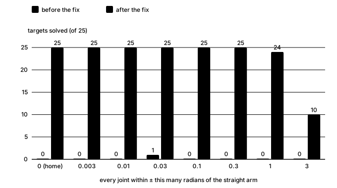
Teleop and planning both lean on ssik, the lab's analytical IK solver, which I didn't write, and on the OpenArm it kept failing. I traced it to a singularity in the solver itself: the OpenArm's joint axes meet at shared points, so its link lengths are zero and every twist is a right angle, and that exact geometry breaks the Raghavan–Roth elimination the solver uses. My fix nudges those zero lengths by a tiny fraction of the arm's size, so the solver works on an arm a hair off the real one, then, since forward kinematics is cheap, refines the answer against the true arm's FK, step after step, until it's an exact solution again. The maintainer confirmed the fix would have worked while landing the same one upstream.

Bar chart of IK targets solved on the OpenArm, 25 per distance from the straight arm, from 0 to 3 radians: before the fix, 1 of 200 in all; after it, every target out to 0.3 radians, 24 at 1 radian and 10 at 3
My July OpenArm IK (ssik's joint-lock solver) on 200 random reachable targets, run again with ssik just before my fix and with it: 1 solved before, 184 after.

Fleet RL

Resetting the peg without a person

Code

Also shows: Robot learningMotion planning

In online RL an arm practises a task over and over, so after every try something has to put the peg back where the task starts. I built that reset for the peg-insertion task. A teammate and I designed the tagging together, and they wrote the code that reads it: ten AprilTags on the peg's faces, from which the scene camera solves the peg's full pose. I calibrated each camera with a ChArUco board, first its lens (the intrinsics), then its pose relative to the arm (the extrinsics). For the second, a calibration script has the arm set the tagged peg down at a grid of spots on the board and fits the arm's joint zeros and the camera's pose to where the arm thought the peg was against where the camera saw it. With that, the reset finds the peg anywhere in the workspace, works out how it is lying, and plans every waypoint of the pick and the place before the arm moves, choosing the grasp the arm can reach with the least travel within its joint limits. It then checks where the peg landed. This lets the teammate's automatic success detection score each try, so the arms can run online RL on their own. The reset has run on a real arm; the clip shows the same planner in simulation.

Four resets from four scrambled spots, planned by the reset code and shown in simulation at 2× speed.
Four views of the square peg with a tag on the top, the bottom and two on each side face, numbered 0 to 9, with a red arrow marking each tag's top edge
Where the ten tags go on the peg.

Advanced Robotics at UW

A test platform against motion capture

Code

Also shows: Experiment design

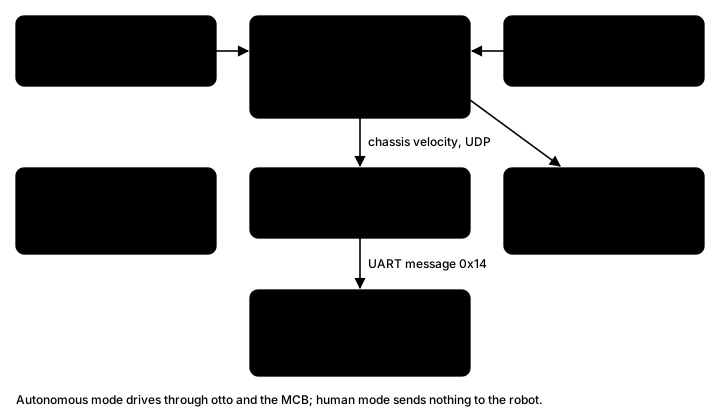
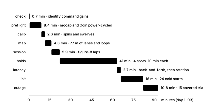
The sentry localizes with an Odin1, a lidar-inertial sensor that relocalizes into a prebuilt map. Before the team decided whether the whole localization system could rely on it alone, we wanted to know how accurate it is and where it is weak. So I built a test platform that measures it against the motion capture room, whose OptiTrack tracks the robot to a fraction of a millimeter. It starts and stops the sensor, records every run, guides whoever is driving with live mocap feedback, and can also drive the robot itself through the Jetson and the robot's controller, with a watchdog and speed caps. A campaign day runs a fixed protocol: calibration spins, a mapping drive, figure-8 laps at set speeds, ten-minute holds, back-and-forth motion to measure latency, cold starts, and outages where someone covers the sensor.

Diagram of the system: motion capture and the Odin1 sensor feed the characterization scripts, which record every run and write a report; in autonomous mode they send chassis velocities over UDP to the Jetson, which forwards them over UART to the sentry's motor control board
The three parts, and the default human-driven mode.
Bar timeline of day 1: preflight 8 minutes, calibration 3, mapping 5, figure-8 laps 6, holds 41, latency 3, cold starts 16, outages 11; 93 minutes in all
Day 1, step by step, from the campaign's time estimate.

OpenDubs

Two 2D lidars, merged into one scan

Also shows: State estimationROS 2Hardware bring-up

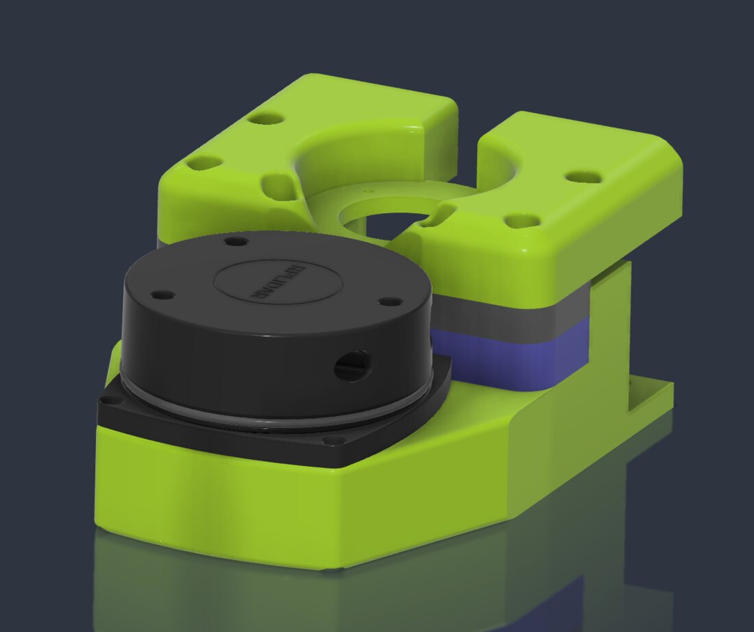
For localization and a map, the base carries two RPLIDAR A1 2D lidars, one at the front and one at the back. Bringing them up, with the team, was mostly fighting USB: the two units have identical USB IDs, so udev rules name each by the hub port it's plugged into, and they power up a few seconds apart so neither times out.

Mapping and Nav2 expect one scan, so I wrote a node that merges the two. The two scans never line up on their own: nothing guarantees the lidars spin at exactly the same rate or finish a revolution at the same moment, and each reaches the Thor with its own latency. So the node pairs scans by their timestamps (any two within 0.1 s), looks up each scan's transform into the robot's frame at that scan's own timestamp, resamples both to the finer of the two angular resolutions, and keeps the nearest return in each direction of one 360° scan, stamped halfway between the two and dropping hits on the robot itself. On top of it, I set up slam_toolbox and Nav2, which drove the robot point to point in simulation.

A CAD render of a round 2D lidar sitting in a bright green 3D-printed mount
One of the two lidar mounts. CAD render from the lab's build guide.
A replay in Gazebo: the robot's URDF, my lidar merger and our slam_toolbox settings, unmodified, mapping a made-up lab room while Nav2 drives. 6× speed.